Skip to content

Frame and Logistics for Marianne Nicolson’s exhibit at Denver Art Museum

Mounting Design and Render – C Gabriel

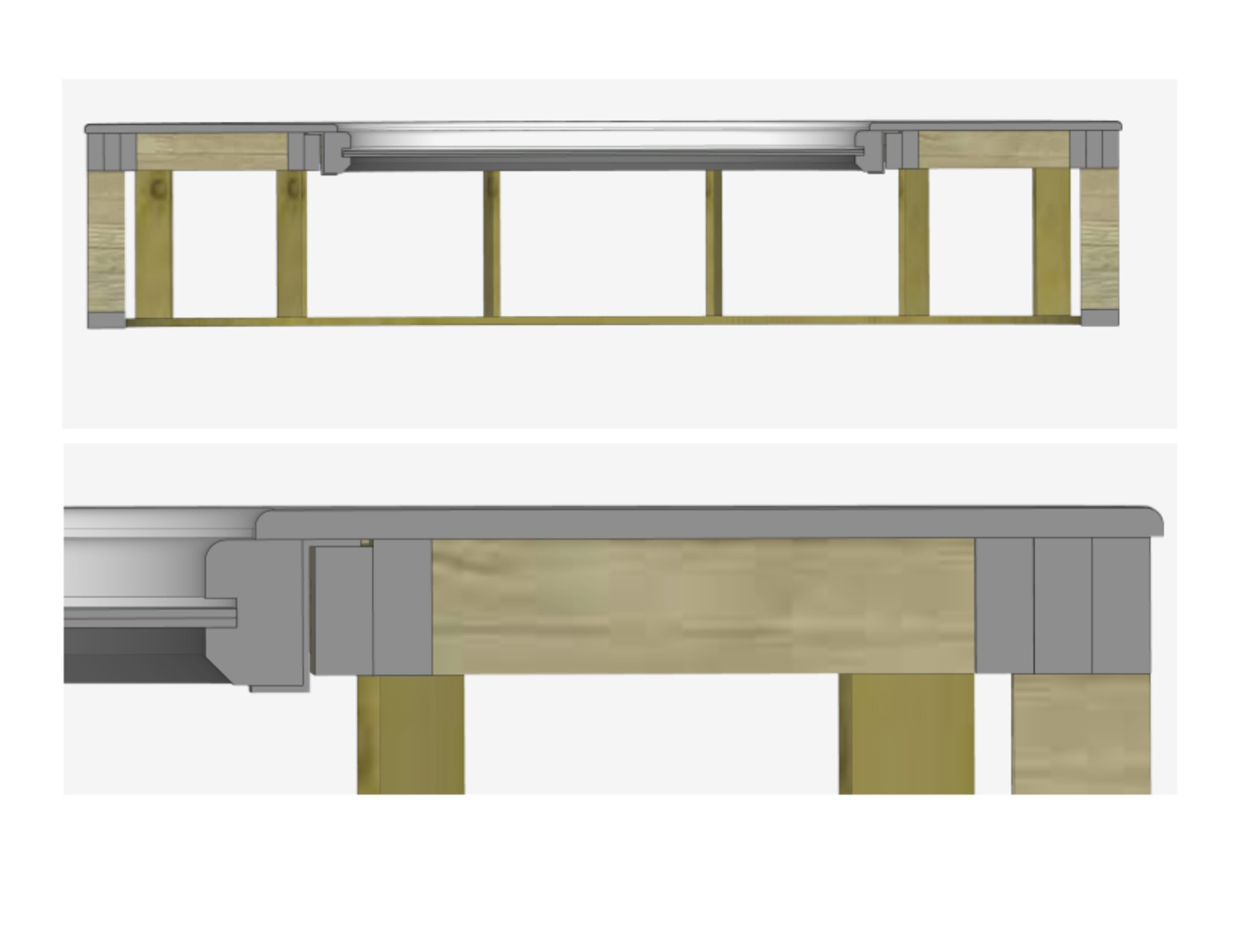
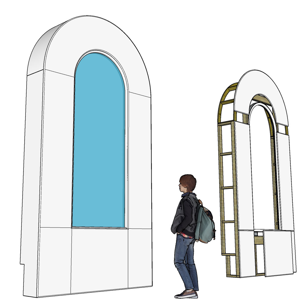
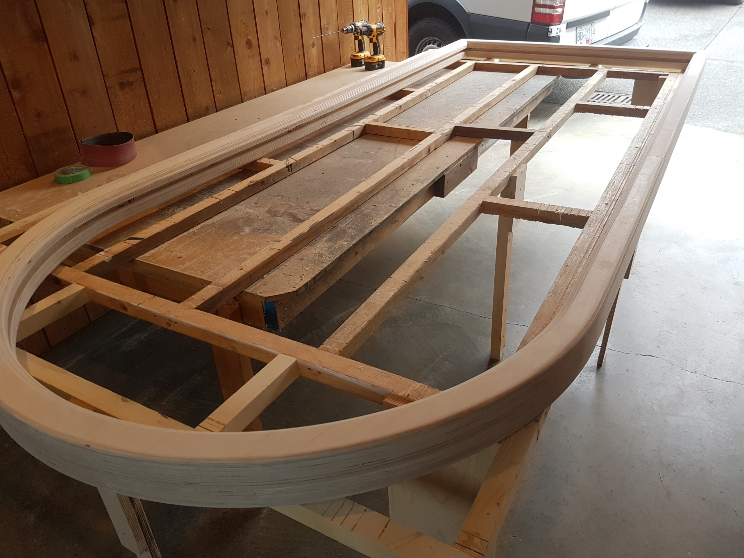
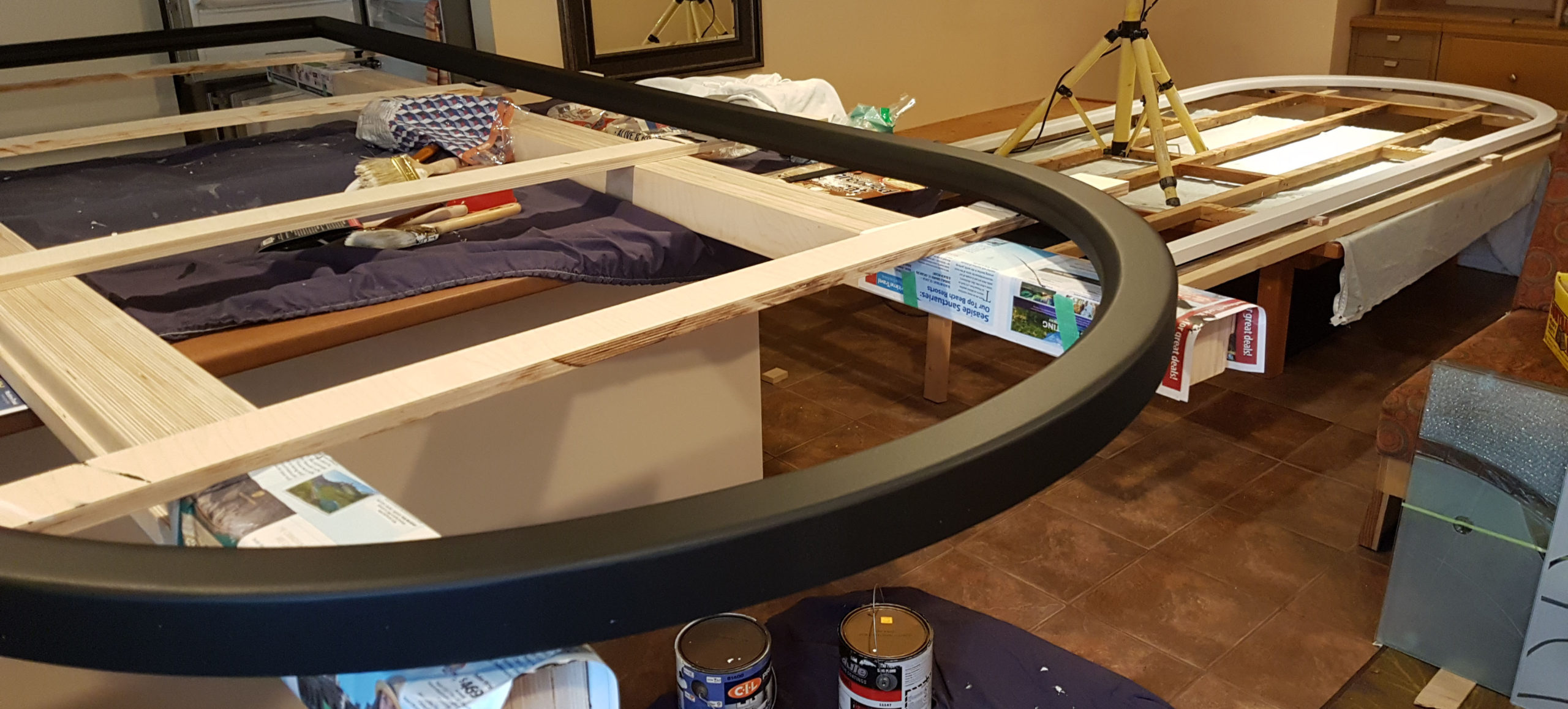
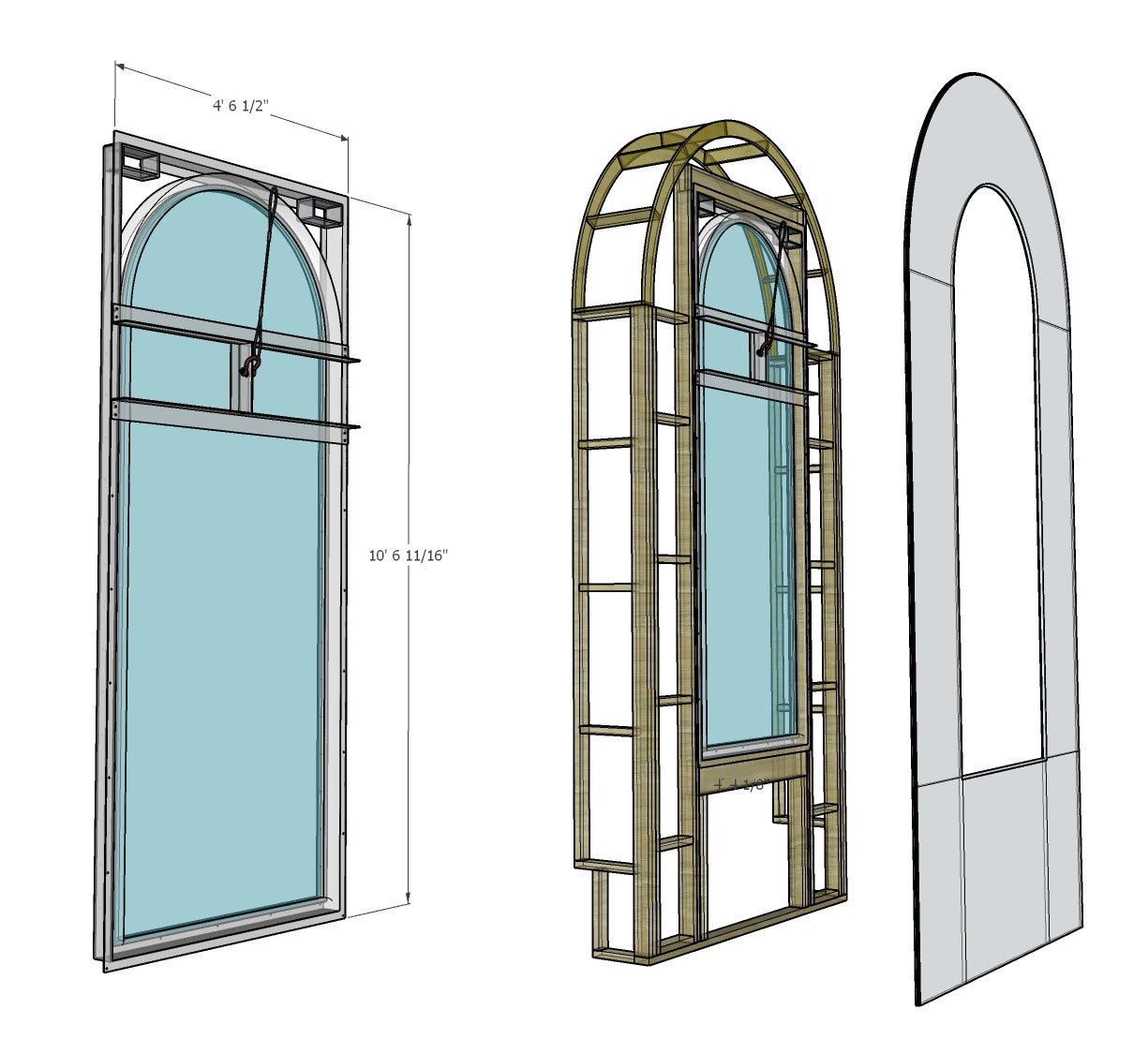
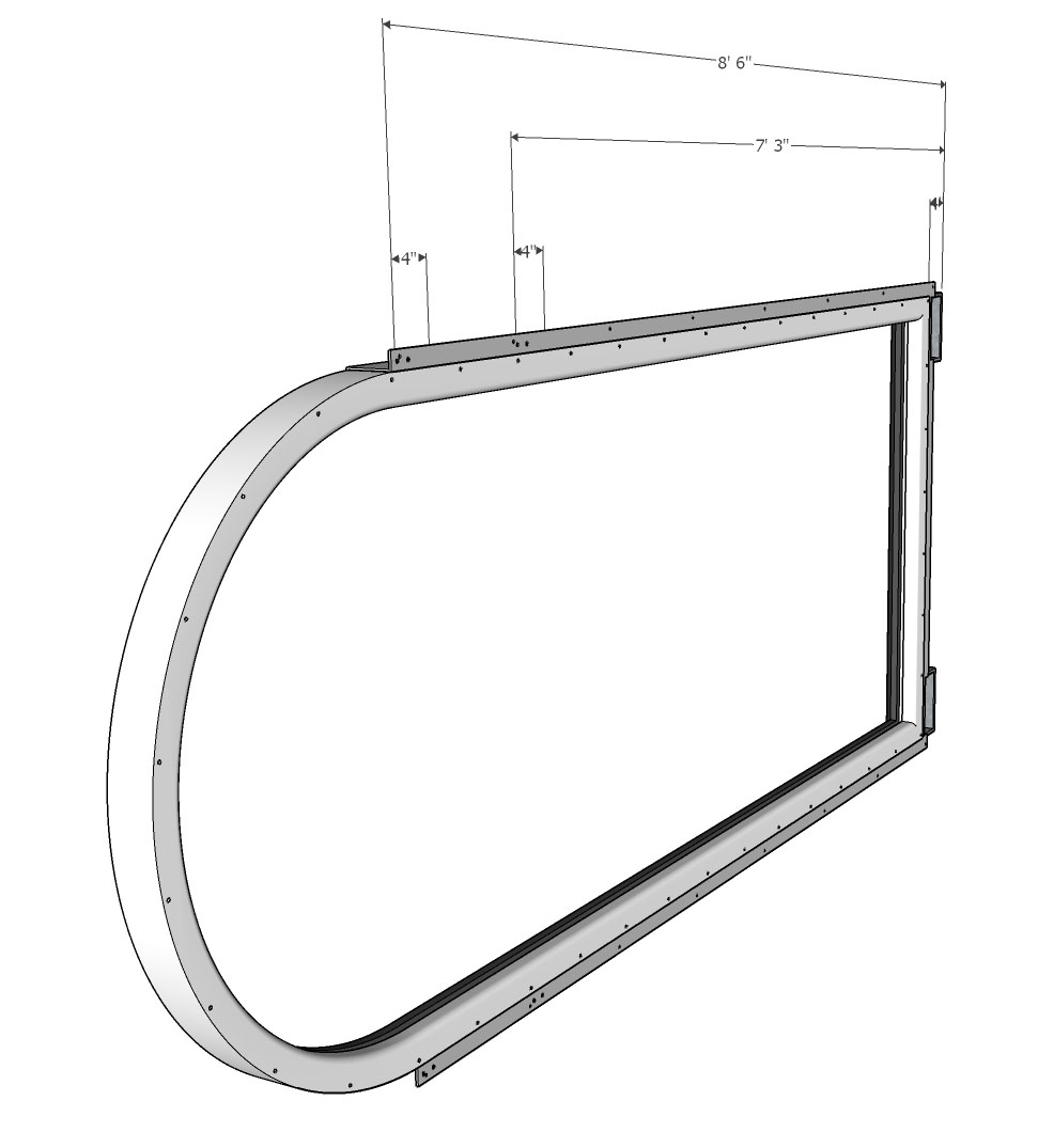
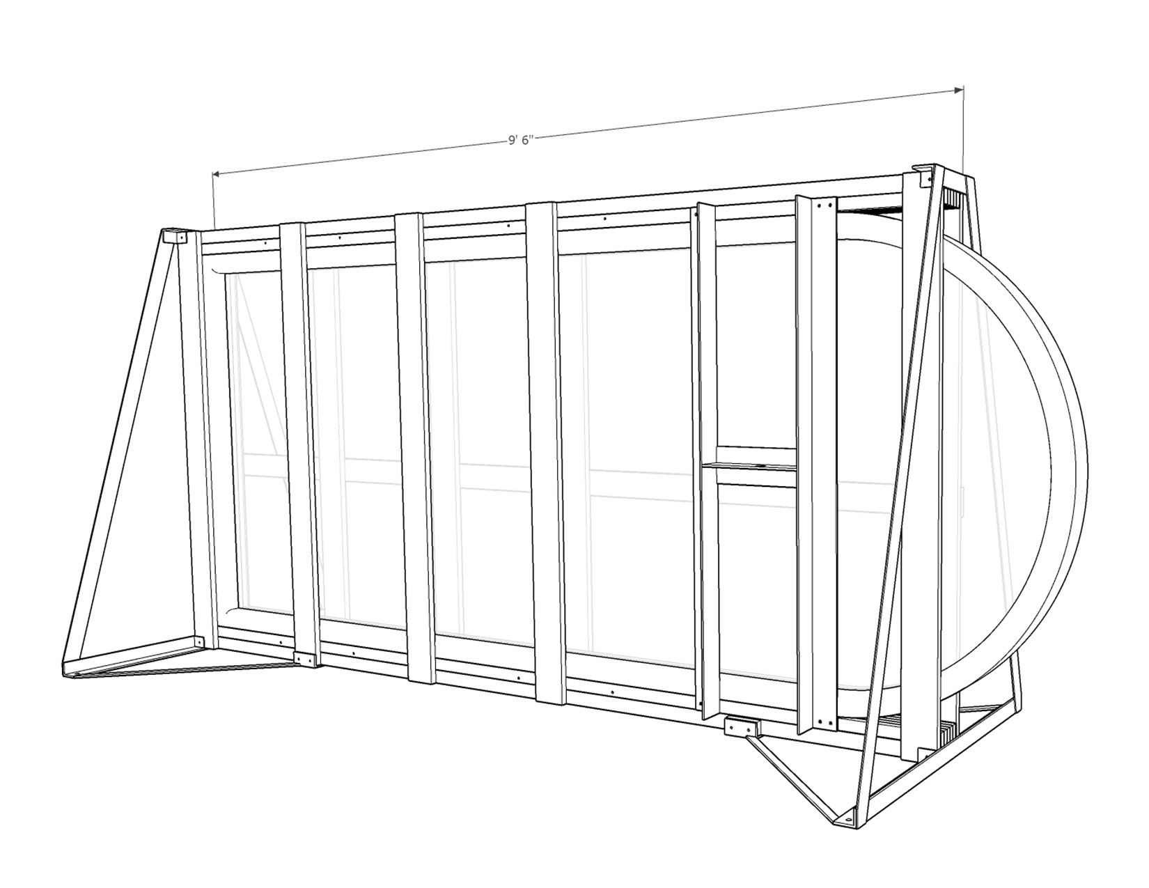
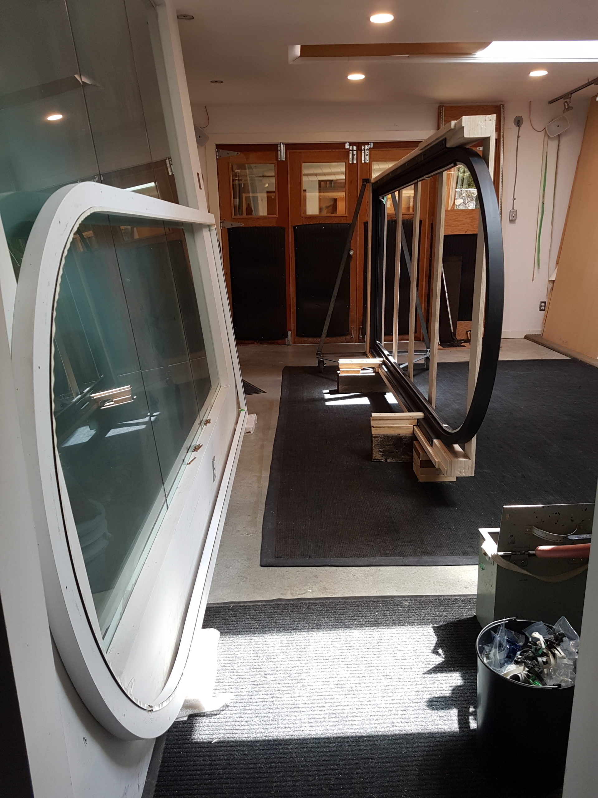
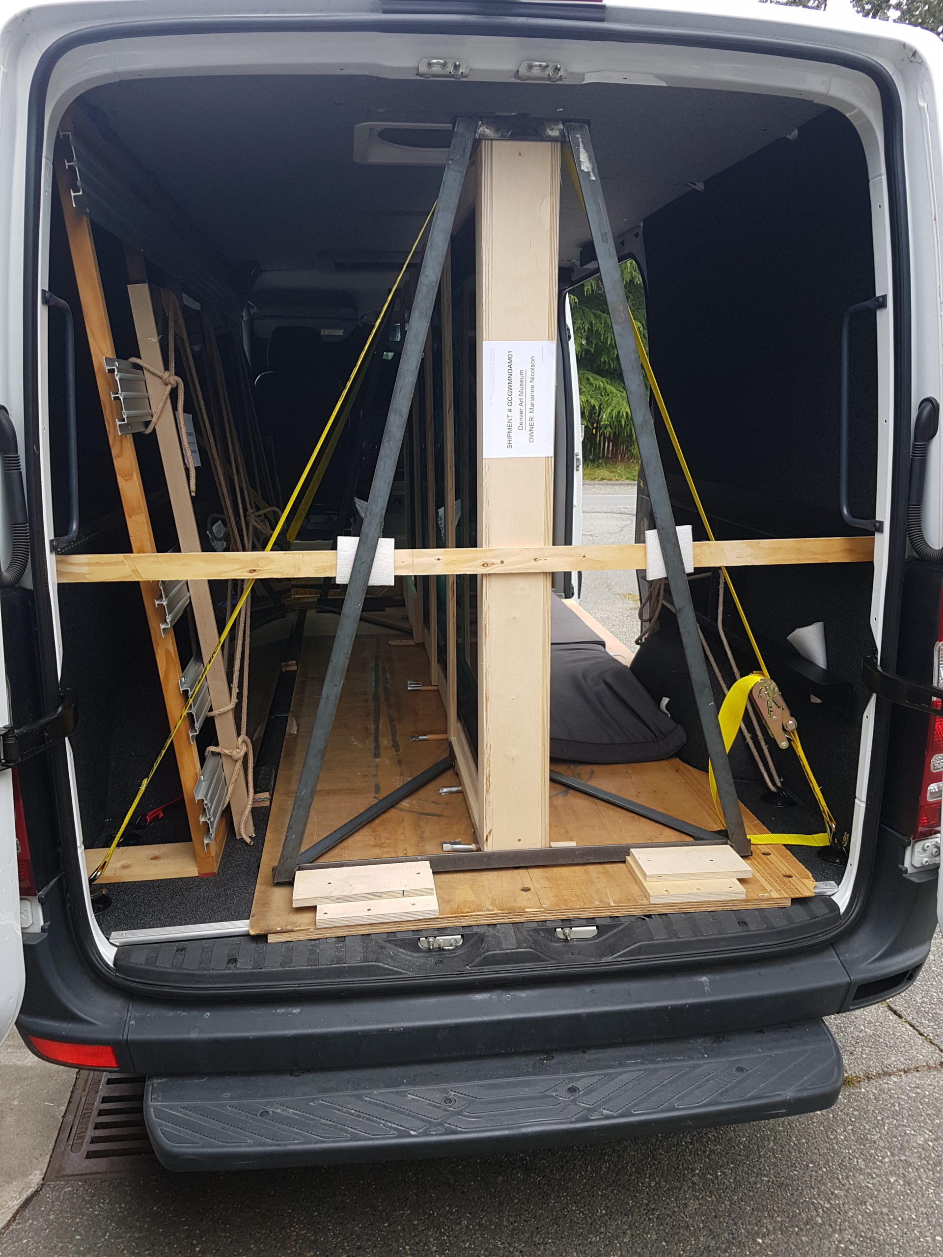
I had to figure out a way to frame, handle, and mount a 300lb piece of glass for Marianne Nicolson’s exhibit at the Denver Art Museum. After consultation with the team at DAM about their space and lifting ideas, I began with models and built from there.

The fabrication began by roughing out and laminating multiple layers of 5’x5′ Baltic Birch plywood for each side of the frame to keep the profile low and stable.

The now-laminated frame sides retained some cross-bracing to keep their shape and provide a trammel point for my radius jig.. Frame blanks were cut to final size and received the rabbet to accept the glass.

With bracing removed and wood filled and sanded, I added a 45 degree chamfer to the inside edge to minimize any shadowing from the directional lights inside the finished assembly. The front side received a 3/4″ round over.

The inner half is painted a flat black to prevent unwanted light refraction, and the outside in a plain, re-paintable white.

Metal Lift, Frame Design & Render – C Gabriel

The frame is designed to be strengthened by a steel flange. This will double as a lifting mechanism by incorporating a removable cross-member, and also as a mounting bracket into the final wood structure – being built concurrently on site in Denver Co.

(Here the forklift boxes are seen at the top, but the lift height limit of the onsite equipment dictated they be moved to the bottom. How did we manage to live so long without modelling…? 😉 )

Metal Frame Support Design & Render – C Gabriel

This model, and the photo below show the design for the steel “S” shaped flange, with ‘lift boxes’ attached now at the flat end for use by the onsite forklift.

The welded steel is sandblasted and then powder-coated.

The inner wood frame (black half) is screwed to the steel mounting flange (from the back side- not shown). The outer frame (white half) is dry fit and the lifting brace is temporarily attached.

The steel mounting flange is secured to 9′ long laminated plywood transport rails (made from frame material off-cuts) that will become the crate sides and supports for handling.

Crate and Rolling A-Frame Design and Render – C Gabriel

Two steel A-frame brackets will stabilize the crate, and with wheels attached, allow it to be rolled easily into the facility.

The crate takes shape with one side attached firmly and dunnage set up to assist the 300lb glass glazing.

Once installed, the glass is secured by the outer side (white) of the wood frame, followed by the rest of the crate cleats and the second metal A-frame to complete the transport assembly.

Complete assembly with wheels attached (and an additional “nose box” to clear the gap at the back of the vehicle while the wheels are temporarily removed) for transport.

The 650lb + crate assembly now rolls easily into the van.

With wheels temporarily replaced with dowel rollers to slide it in – its time for a road trip.

Lift Mechanism Design & Render – C Gabriel

On site, using lift equipment, the hook hole in the center of the cross-member will be used to hoist the work into vertical position, allowing forklift access to lift boxes welded into the base of the steel mounting flange.

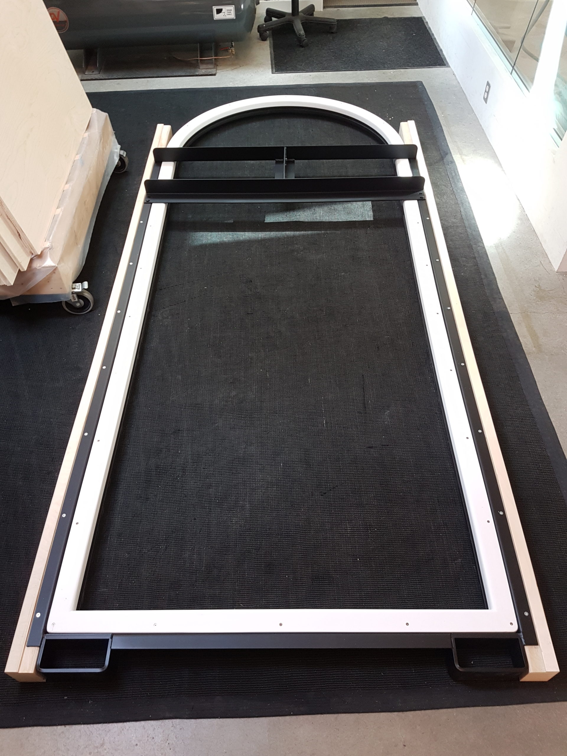
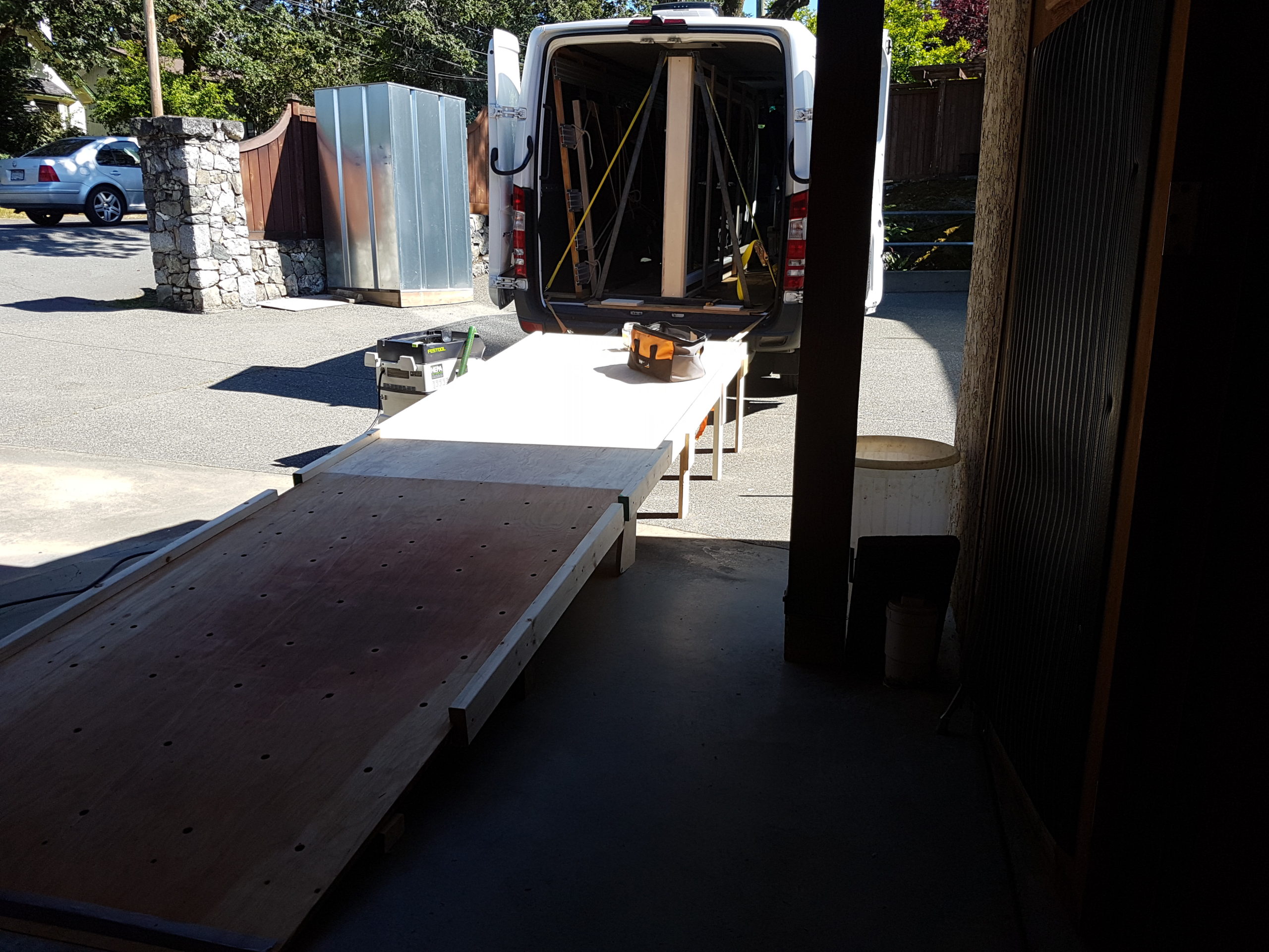
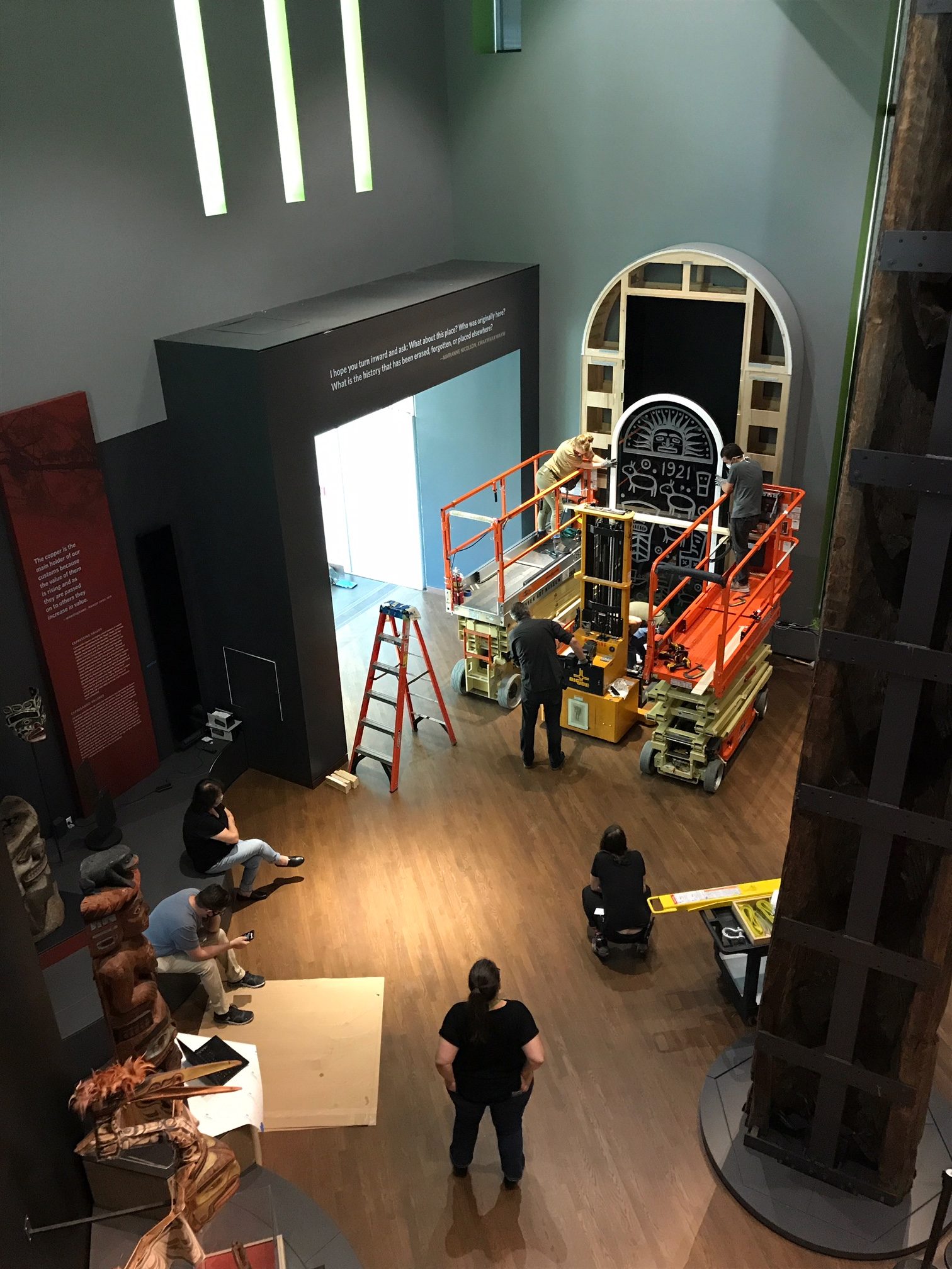
By all accounts, the install went smoothly ( photo courtesy of DAM).

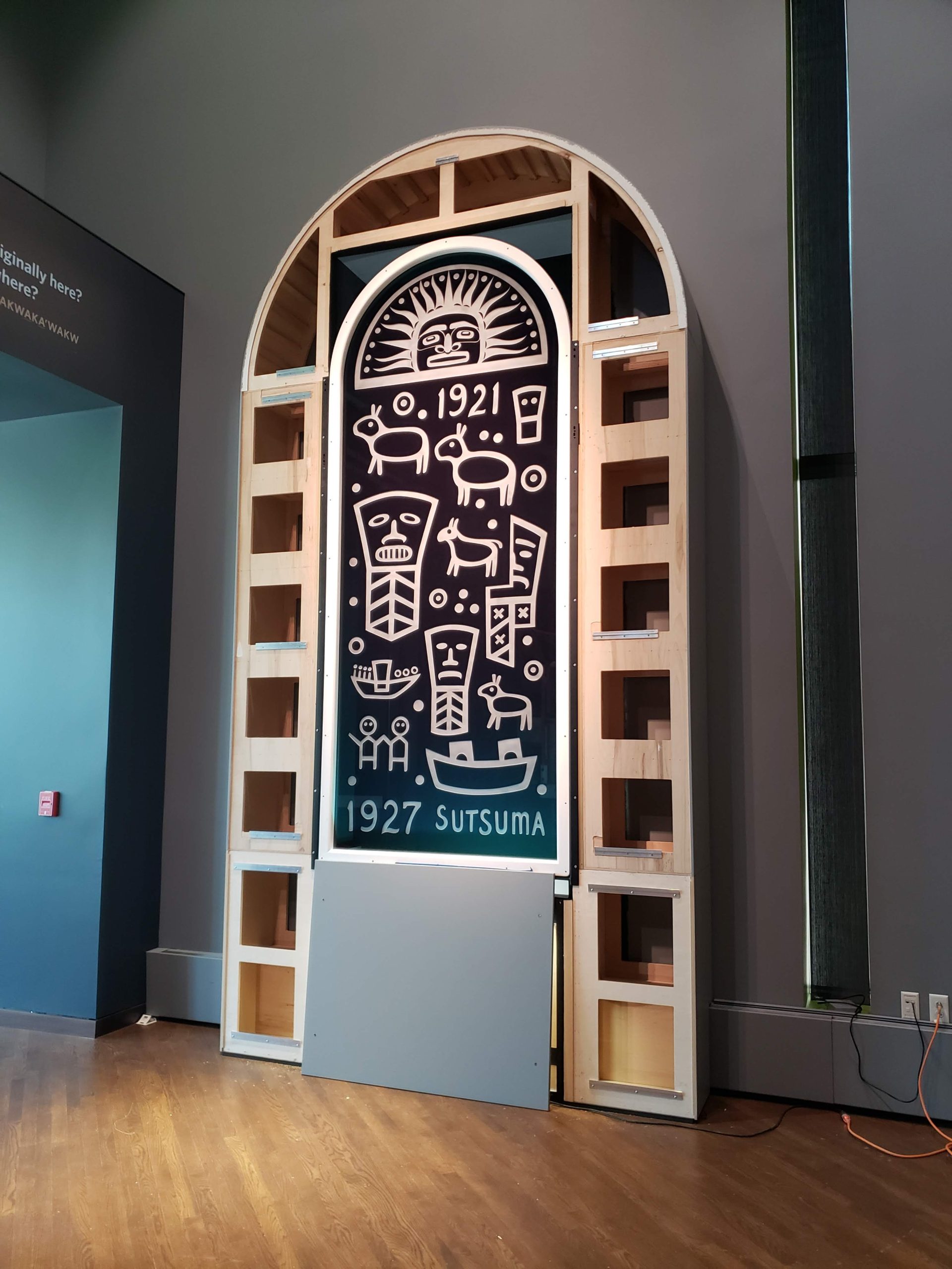
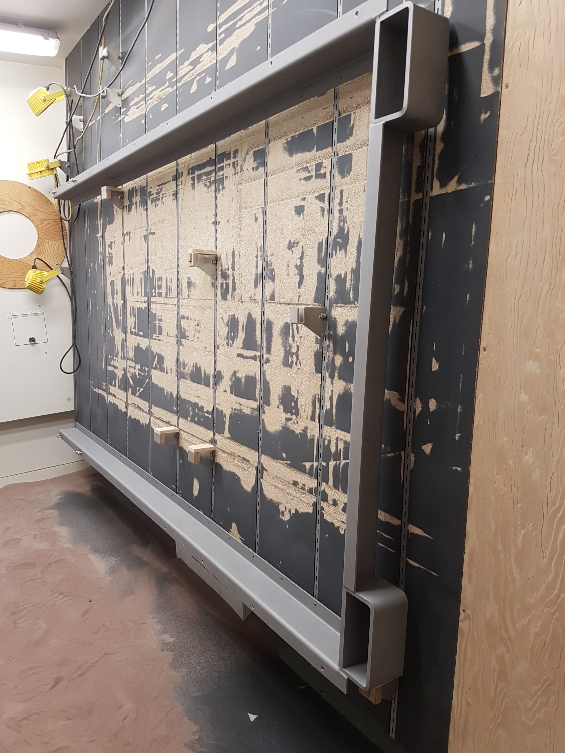
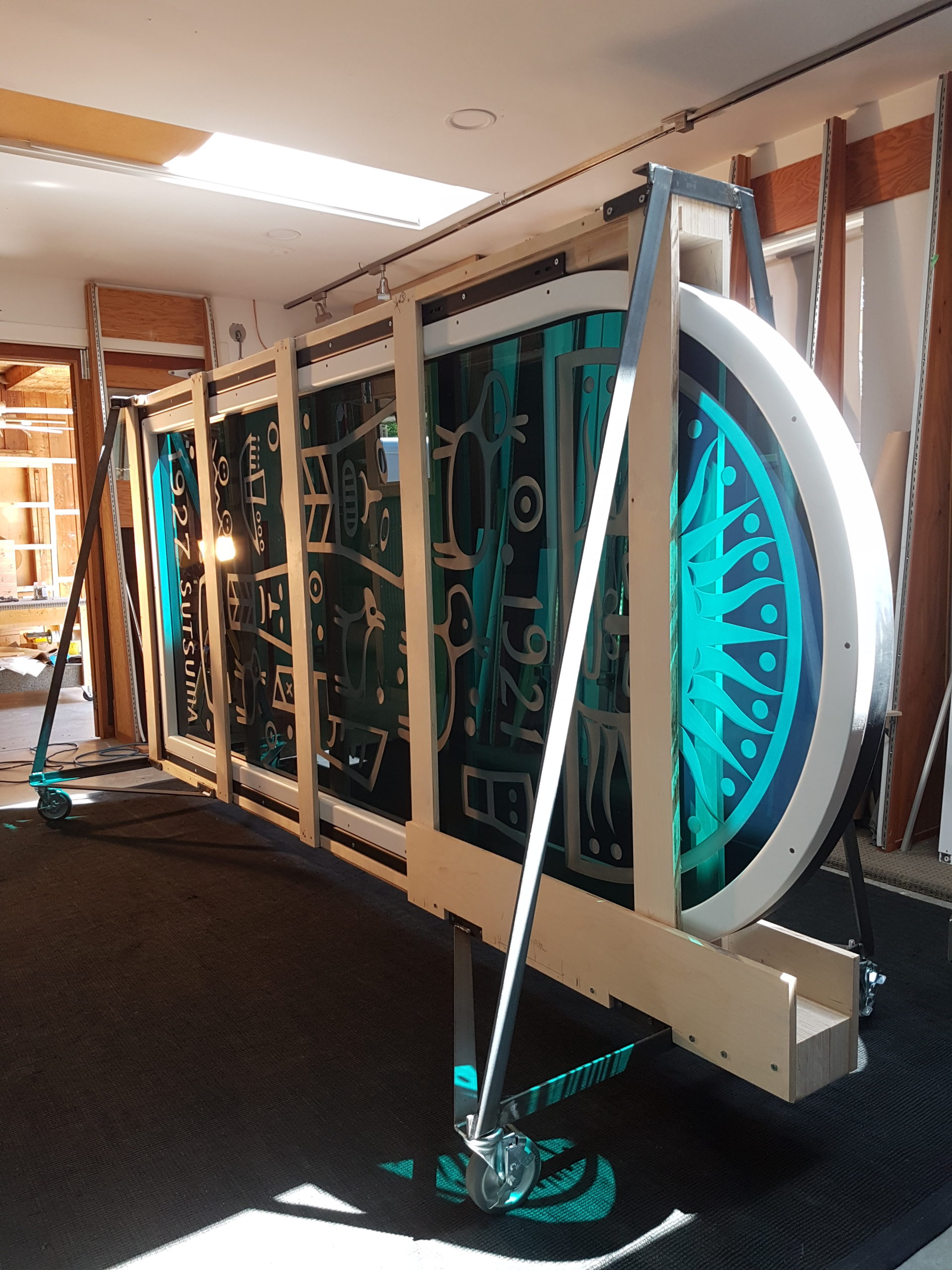
The lighting and face panels still to come… (photo courtesy of DAM ).

Published inGlass CarvingModellingWoodworking

Be First to Comment

Leave a Reply